
Based on some of the comments from the previous post, I am going to take a couple of steps ahead and cover creating a custom variable that can be passed to the Parts List in Civil 3D. This post is assuming you already understand the basics of Part Builder and know how to model a structure. If not don’t worry, we will be getting back to the basics in Part 3.
Step One (Note: it is very important that these steps be followed in exact order), click the options button at the top of the Content Builder as shown.

 In the Options dialog box check the Custom Sizing Flag and click OK. What this does is allow the ability for us to create a custom variable and then later adjust that variable in the xml files that will allow the custom variable to be visible in the Part List. This is an important step, because we can still create the custom variable in Part Builder, but if this option is not checked then certain information for that variable will never come through after editing the xml files and then never be available in the Parts List.
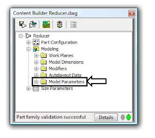
Step Two, create the initial variable. In the Content Builder go to Model Parameters right click and select Edit.

In the Model Parameters click New and you will get the following dialog box.
In the Model Parameters click New and you will get the following dialog box.
 In this example I am creating a parameter that I will use for an inline reducer structure I created. I am already using SID, the Inner Structure Diameter for the diameter coming into the structure. So I need another parameter for the reducing diameter coming out of the structure so that I will be able to create multiple part sizes in Parts List from a single structure. Make sure you keep in mind or write down the exact name and description of the new parameter just created, because we will need to add that exactly as it is here in one of the xml files. For now just use a constant value for the Equation because we will modify this in the Size Parameters.
Step three, modify the size parameters. Right click on Size Parameters, as show below, and select Edit Configuration.
 In the Parameter Configuration dialog box, shown below, find your new variable. We will want to modify this variable here as much as we can to be what we want so there will be less to do in the xml files.
In my variable RID, the Reducing Inner Diameter, I have changed the Data Storage type from a constant to a List, that way I can go into the values for this variable and add all the sizes that I will use to create this part in Parts List. We also want to change the Visible attribute from False to True; this is part of what will allow us to see this variable in the Parts List when adding sizes. Now look at the Context and Index Attributes for this variable, shown above in the box, these are the pieces of information that we will need to modify in the xml files that will allow the variable to pass to the Parts List. You’ll notice that in the context of this variable that it is calling it a Model Distance Parameter, where the other variables have a specific context matching the variable itself. This is because the context for this variable does not exist in the xml file, so we are going to have to add it. Also you will notice the Index of this variable is set to 1, were the others that pass to the Parts List are 0, we will have to modify this as well in the xml file.
Step four, edit the xml files. Make sure you save your structure and exit Part Builder, and close Civil 3D before we edit the xml files. Once everything is saved and closed there are two xml files we need to edit. The first will be the xml file for the structure itself which will be located in …/Pipes Catalog/US Imperial Structures/Your Chapter/Reducer.xml, where … is the location on your system for the Pipes Catalog and Your Chapter is the chapter you created at the time you created or saved the initial structure. The second xml file to edit will be …/Pipes Catalog/Aecc Shared Content/AeccPartParamCfg.xml, this is the xml file that will read the context of the structure and eventually allow us to pass this variable to the Parts List.
Open the structure xml file with notepad.

Find your new variable as shown highlighted above. Then find the context and index for this variable also shown highlighted above. Change the context to be something similar to the description with no spaces, for this variable I used “StructReduceDiameter”. Then change the index to “0”. Remember to keep the parenthesis on these attributes. Save and close the xml file.
Now open the AeccPartParamCfg.xml file.

In this xml file the new variable does not exist, so we have to create it in two places. In this case the easiest thing to do is find a variable that is similar to the one you created; the RID variable is similar to the SID variable. Do a search for SID copy the line and paste into a new line as shown highlighted above. Edit the variable name, description and context to match what is in the structure xml file.
Now we need to add the context to the Structure Domain.
 Find the Structure Domain towards the bottom of the xml file or do a search for the context of the variable that is similar to the one you created. It is very important in this step to make sure we add the context of the new variable in the appropriate Domain type. In the case of the inline reducer, I created it as a Junction Structure, so I added the context of “StructReduceDiameter” in the Junction Structure category, as highlighted above. Save and close the xml file.
The final step is to verify that everything works. Reopen your structure in Part Builder and go to the Size Parameters, Edit Configuration.

You will see by the highlighted information above that the Context and Index of the variable is now reading the information that we edited in the xml files. Exit Part Builder and go to your Parts List in Civil 3D add the Part Family for the structure if not already in your list and go to Add Part Size.
 You will see by the highlighted information that our custom variable is now available in Parts List.


